IR Controller
Project Overview
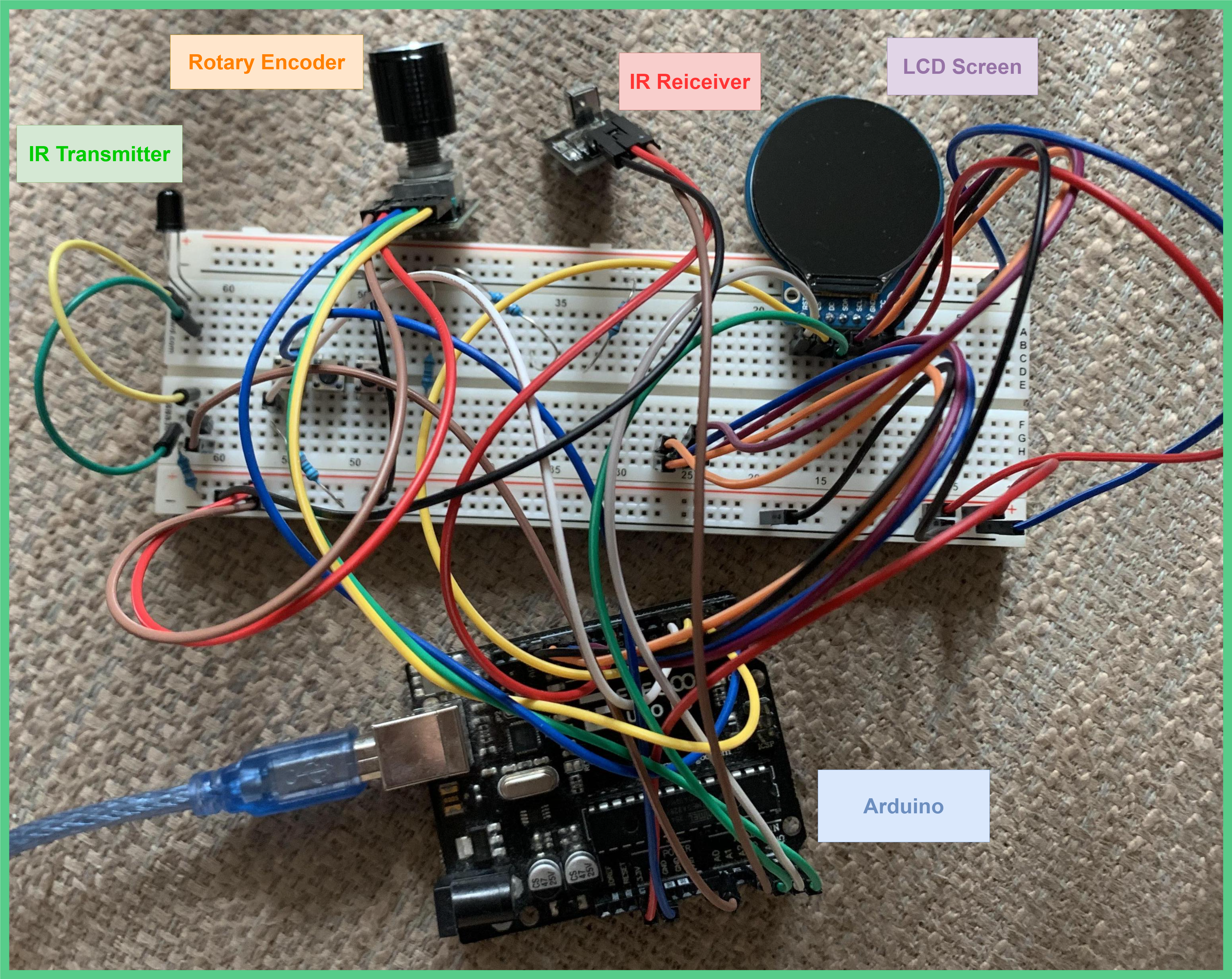
I am working on a “smart watch” with IR and radio control capabilities. The images and videos below depict an Arduino protoype of the device. The project is coded in C and I used PlatformIO (an open source development platform for embedded systems that is accessed through VSCode) for developing and deploying code. The current prototype only has functionality for IR signals which are described below. Some of the documentation is still in progress.
Current Capabilities:
– Copy IR signals from a source
– Save IR signals
– Send IR signals
– Name IR signals
– Delete IR signals

Functions:
Send Signal
The demo above shows the Arduino prototype sending signals to the TV. The signals were saved to the Arduino before the presentation. The IR transmitter only works at short distances. I am assuming this is due to a low current output by the Arduino (the IR transmitter is rated for up to 100mA but an Arduino GPIO pin has a max output of 40mA). This problem will be addressed in the future, but this proves the concept.
Copy and Save Signal
Delete Signal
Rename Signal
Programming
Encoder Commands
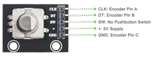
The encoder is the input device for the IR controller. Mechanically, it can be rotated or pressed.

A struct was made for the encoder. The struct holds pointers to global variables that are updated when the encoder is rotated or pressed.
Encoder Struct
typedef struct{
    volatile int* currentPosition;
    int lastPosition;
    volatile bool* CLK_state;
    volatile bool* DT_State;
    volatile bool* ButtonPressed;
}Encoder;
The rotation and button press rely on hardware interrupts. An initalization function is used to make an encoder instance, define the Arduino pins for the encoder, initalize the hardware interrupts, and set the pointers of the encoder instance equal to the addresses of the global variables.
Global Variables Defintions
//true definitions of variables
volatile int encoderPosition = 0;
volatile bool CLK_State = false;    //Output A
// volatile int CLK_lastState;
volatile bool DT_State =false;      //Output B
volatile bool EncoderButtonPressed = false;
Encoder Initialization Function
Encoder encoder_KY040_init(){
  Encoder createdEncoder;
  //define pins
  pinMode(ROTARY_ENCODER_CLK, INPUT_PULLUP);
  pinMode(ROTARY_ENCODER_DT, INPUT_PULLUP);
  pinMode(ROTARY_ENCODER_SW, INPUT_PULLUP);

  //set interrupt for the encoder button
    attachInterrupt(digitalPinToInterrupt(ROTARY_ENCODER_SW), handleEncoderButtonPress, FALLING); // Trigger on rising edge
  // set interrupt for rotate encoder
    attachInterrupt(digitalPinToInterrupt(ROTARY_ENCODER_CLK), handleEncoderRotate, CHANGE);

  // Initialize CLK and DT pin states
  CLK_State = digitalRead(ROTARY_ENCODER_CLK);
  DT_State = digitalRead(ROTARY_ENCODER_DT);

  createdEncoder.ButtonPressed = &EncoderButtonPressed;
  createdEncoder.CLK_state = &CLK_State;
  createdEncoder.DT_State = &DT_State;
  createdEncoder.currentPosition = &encoderPosition;
  createdEncoder.lastPosition = *createdEncoder.currentPosition;
  return createdEncoder;
}
There are two ISR functions, one for the button and one for the rotation of the encoder.
ISR (Interrupt Serivce Routine) Functions
Button ISR
void handleEncoderButtonPress() {
    EncoderButtonPressed = true; // Set flag to indicate button press
}
Rotation ISR
// Interrupt Service Routine (ISR) for Encoder rotate
void handleEncoderRotate() {
  bool aVal = digitalRead(ROTARY_ENCODER_CLK);
  bool bVal = digitalRead(ROTARY_ENCODER_DT);

  if (CLK_State && !aVal) {
    if (bVal && !DT_State) {
      encoderPosition++;
    }
    if (!bVal && DT_State) {
      encoderPosition--;
    }
  }

  CLK_State = aVal;
  DT_State = bVal;
}
Check Encoder Rotation Function
uint8_t checkRotation(Encoder encoder){
  if(*encoder.currentPosition != encoder.lastPosition){
    if(*encoder.currentPosition > encoder.lastPosition){
      //clockwise turn
      return 1;
    }else if(*encoder.currentPosition < encoder.lastPosition){
      //counter-clockwise turn
      return 2;
    }
  }
  return 0;
}
Since there is only a single button, I made functions to recognize different patterns to distinguish different inputs. I made a function for a button press, a double click, and a button hold.
Button Press Function
uint8_t buttonPress(){
  if(EncoderButtonPressed){
    EncoderButtonPressed = false;
    return 1;
  }
  return 0;
}
Double Click Function
uint8_t doubleClick() {
    // Check start time
    uint16_t startTime = millis();
    uint16_t diff;
    uint8_t doubleClickDetected = 0;
    if (EncoderButtonPressed == true) {
      doubleClickDetected = 1;
    }

    // Loop for short window to see if double click
    while ((diff = millis() - startTime) < 300) {
        // See if encoder button is pressed
        if (digitalRead(ROTARY_ENCODER_SW) == LOW) {
            // Wait for debounce time
            delay(50);
            // Check if button is still pressed after debounce
            if (digitalRead(ROTARY_ENCODER_SW) == LOW) {
                if (!doubleClickDetected) {
                    doubleClickDetected = 1;
                    // Wait for button to be released
                    while (digitalRead(ROTARY_ENCODER_SW) == LOW);
                    // Debounce release
                    delay(50);
                    // Update start time for second press
                    startTime = millis();
                } else {
                    // Double click detected
                    EncoderButtonPressed = false;
                    return 1;
                }
            }
        }
    }
    return 0;
}
Button Hold Function
uint8_t buttonHold() {
    if(digitalRead(ROTARY_ENCODER_SW) == LOW){
      uint16_t startTime = millis();
      uint16_t diff;
      while (digitalRead(ROTARY_ENCODER_SW) == LOW) {
          diff = millis() - startTime;
          if(digitalRead(ROTARY_ENCODER_SW) == HIGH){
            break;
          }
          if (diff > 500) {
              EncoderButtonPressed = false;
              return 1;
          }
      }
    }
    return 0;
}
I made a buttonCommand function that outputs a 1, 2, or 3 depending on which button function (buttonHold, doubleClick, or buttonPress) is exectuted. This function is easier to call in the main loop because I can call buttonCommand instead of calling each button function individually.
Button Command Function
uint8_t buttonCommand(Encoder encoder){
  while(digitalRead(ROTARY_ENCODER_SW) == HIGH || EncoderButtonPressed == false){
    if(*encoder.currentPosition != encoder.lastPosition){
      return 0;
    }
  }
  if(buttonHold()){
    //EncoderButtonPressed = false;
    return 3;
  }
  else if(doubleClick()){
    EncoderButtonPressed = false;
    return 2;
  }
  else if(buttonPress()){
      return 1;
    }
  EncoderButtonPressed = false;
  return 0;
}
LCD Functions
Documenting in progress
An LCD driver and a basic functions for drawing characters, words, and simple shapes was provided for the LCD screen on the manufacturer website.
I made custom function “centerString” which allowed me specifiy a row on the LCD screen and write a string that was centered on the specified row.
//center string on LCD row
PointCoordinates centerString(const char *str, sFONT* font, int row, uint16_t color_background, uint16_t color_foreground, int clear) {

  PointCoordinates startingPixels;                //variable to hold pixel coordinates to where the string will start
  startingPixels.x = 0;
  startingPixels.y = 0;

  //check if row selected is outside circle
  if(row < 0 || row > 239){
    return startingPixels;
  }

  int stringWidth = font->Width * strlen(str);      //calculate string width
  int centerX = 120;                                //calculate string width
  int startX = centerX - (stringWidth/2);           //starting x coord

  //adjust of starting poistion being less than 0
  if(startX < 0){
    startX = 0;
  }

  int startY = row;   //starting y coord

  //do not clear
  if(clear == 0){
  Paint_DrawString_EN(startX, startY, str, font, color_background, color_foreground);
  }

  //clear
  else if(clear == 1){
    Paint_DrawString_EN(startX, startY, str, font, color_background, color_background);
  }

  startingPixels.x = startX;            // store startng pixelX
  startingPixels.y = startY;            // store starting pixelY
  return startingPixels;
}
The “centerString” function is used when showing the names in the selection menu for the IR signals.
Copy Signals
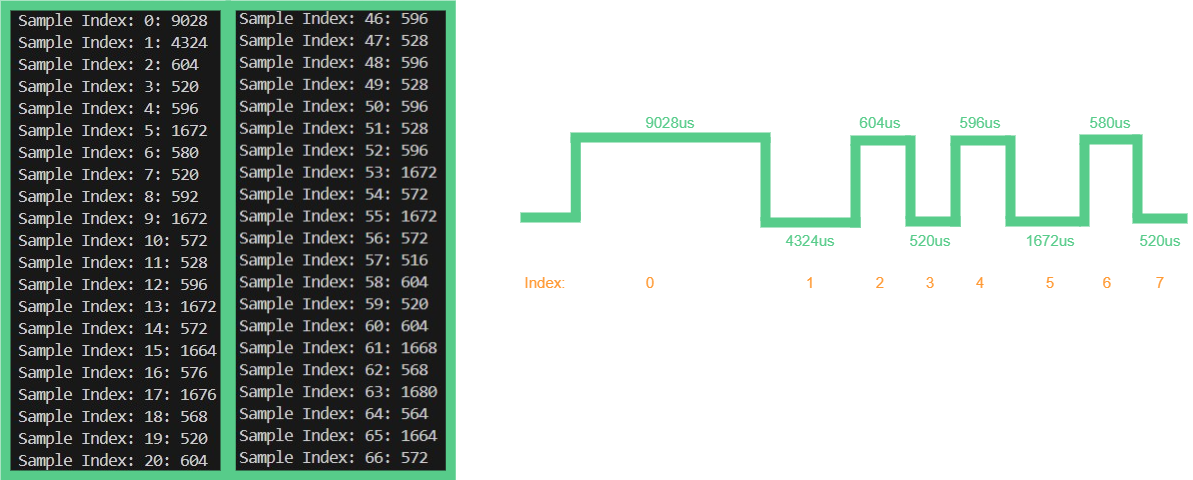
The device is able to copy signals using an IR reciever and send them back out with an IR transmitter. IR remotes work by sending a sequence of high and low pulses to a receiver. For many remotes high IR pulses signify the start of a new signal and the duration of the following low pulse determines if the sent signal represents a 1 or 0. For example, the specific remote I worked with started a new signal with a 9000us high pulse followed by a 4300us low pulse. After the initial pulses, a high pulse ranging from 570us-605us would be used to seperate low pulses. The remote would send 2 lengths of low pulses, one around 1670us and the other around 520us. One of the durations represents a 1 in binary and the other represents a 0. In this case, I am not sure which is which because decoding the signal is not necessary for this function as the signal only has to be replicated by the device and not understood.
 The above image shows the first 20 and last 20 signals of a captured IR signal from a remote. The signal on the right represents the first 8 pusles of the captured signal.
The copied IR signal is saved to a variable that is of custom type, “IRSignal”. The IRignal stores the durations of each of the copied pulses and the total number of pulses copied for a given IR signal.
 Custom struct made to store results of a copied signal. The “pulse_durations” is an array that stores all the time durations in microseconds of all the pulses captured during the signal copy funciton. The “length” variable is the number of pulses captured for a copied signal.
Copy Signal C Function
The microcontroller begins saving the durations of the pulses after detecting a high pulse on the IR reciever pin. A new pulse duration is saved when it detects a change in the state of the IR reciever pin. It stops saving signals when the receiver pin does not change state for more than 0.3s which signifies the end of an IR signal. The code below shows the C function I made to copy the signal.
int copyIRSignal(IRSignal* sample){

    digitalWrite(IR_TRANS_PIN, LOW);    //disable IR transmitter to prevent interference
    digitalWrite(EN_IR_REC, HIGH);      //enable IR reciever

    //wait for receiver to settle after being activated
    while(digitalRead(IR_REC_PIN) == LOW){
        ;
    }
    EncoderButtonPressed = false;                               // set initial state of encoder button
    bool PinState;                                              // define varaible to track pin state
    signalStarted = LOW;                                        // Initially set detected signal as false
    sample->length = 0;                                         // initalize sample index to 0
    centerString("Scanning", &Font20, 120, BLACK, GREEN, 0);    // notfiy user that device is scanning for signal
    delay(50);

    //wait fo signal to start
    while(!(signalStarted)){
        // check reciever pin to see if a signal is being recieved
        if(digitalRead(IR_REC_PIN) == LOW){
            signalStarted = true;               // signal has started
            lastTime = micros();                // initialize lastTime
            currentTime = micros();             // initialize currentTime
            PinState = LOW;                     // initialize pin state
            break;
        }

        //if button is pressed cancel signal capture function
        if(digitalRead(ROTARY_ENCODER_SW) == LOW){
            break;
        }
    }
    //Record signal while signal is active and pulse widths are less than 30ms
    while(signalStarted){
        // if pinState changes then new pulse width has started. Save old pulse width
        if(PinState != digitalRead(IR_REC_PIN)){
            currentTime = micros();                                                 // record time when new pulse width starts
            sample->pulse_durations[sample->length] = (currentTime - lastTime);     // calculate old pulse width and save it to sample array
            sample->length += 1;                                                    // update pulse_durations index
            lastTime = currentTime;                                                 // update lastTime
            PinState = digitalRead(IR_REC_PIN);                                     // update pin state
        }
        // if no pinstate change occurs within 30ms, assume signal has ended
        else if( (micros()-currentTime) > 30000){
            break;
        }
    }

    digitalWrite(EN_IR_REC, LOW);       //disable IR reciever

    //reset IR macros at the end of transmission
    lastTime = 0;
    currentTime = 0;
    signalStarted = LOW;

    //if signal captured
    if(EncoderButtonPressed == false){
        centerString("Scanning", &Font20, 120, BLACK, GREEN, 1);            // remove "scanning" from LCD
        centerString("Signal Captured!", &Font16, 120, BLACK, GREEN, 0);    // notify user of signal capture
        centerString("Signal Captured!", &Font16, 120, BLACK, GREEN, 1);    // remove "Signal Captured!" from LCD
        return 1;
    }
    // if signal capture canceled
    else if(EncoderButtonPressed == true){
        centerString("Scanning for signal", &Font20, 120, BLACK, GREEN, 1); // remove "scanning for signal" from LCD
        centerString("Scan Canceled", &Font20, 120, BLACK, GREEN, 0);       // notify user of canceld scan
        centerString("Scan Canceled", &Font20, 120, BLACK, GREEN, 1);       // remove "Scan Canceled" from LCD
        EncoderButtonPressed = false;
        return 0;
    }
}
Sending Signal
There is also a send signal function that sends a signal through the IR transmitter. The send signal function works by toggling the transmitter ON and OFF for the durations saved in the “pulse_durations” array inside the “IRSignal” struct (shown above). The send signal function assumes a high pulse to begin with, then toggles when starting the next pulse in the “pulse_durations” array until it reaches the end of the array.
Hardware Connections
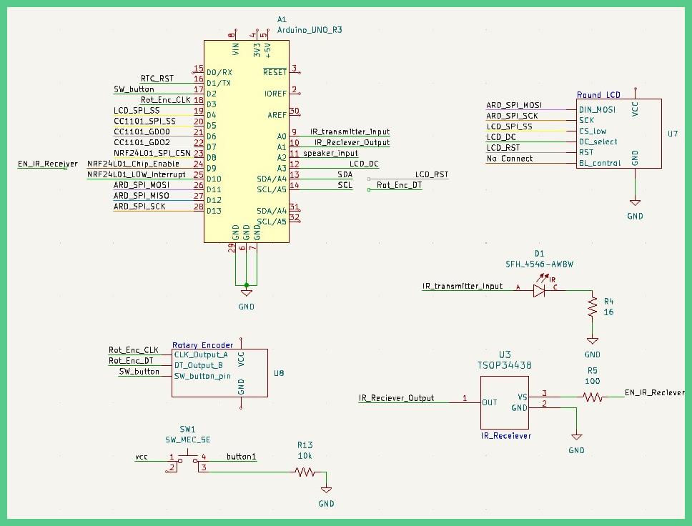
 Wiring Schematic for the Arduino
Most of the pins of the Arduino are used and pins that have two names next to them means two signals are sharing the same pin. The CC1101 and NRF24L01 are signals for two different radio chips that haven’t been implemented yet. Hardware modfications will be made in the future to allow for more GPIO pins.
Future Improvements
The IR features here will eventually be integrated into a “smart watch” that also has similar copying capabilites for radio signals. I may try to add spectrum analyzing features for certain frequency bands in the future to identify signals within a short range of the user, but this may be impossible due to deisgn constraints around size and power. The RAM on the Arduino is almost maxed out, so I am planning to switch to different hardware with more RAM. I may switch over to prototyping with a Raspberry Pi, but before making a decision I need to do more research. The GPIO pins are also maxed out, and so I will need hardware to extend the number of available pins, or reduce the number of pins I am using. I may switch to touch screen to reduce the number of pins needed for controls, and it may provide a more friendly user interface. After testing is complete and code has been made, I plan to make a PCB for the watch and 3D print an enclosure.