BMS Circuit Design
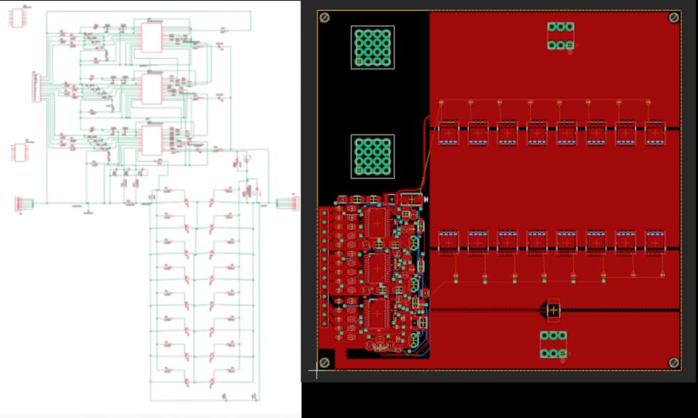
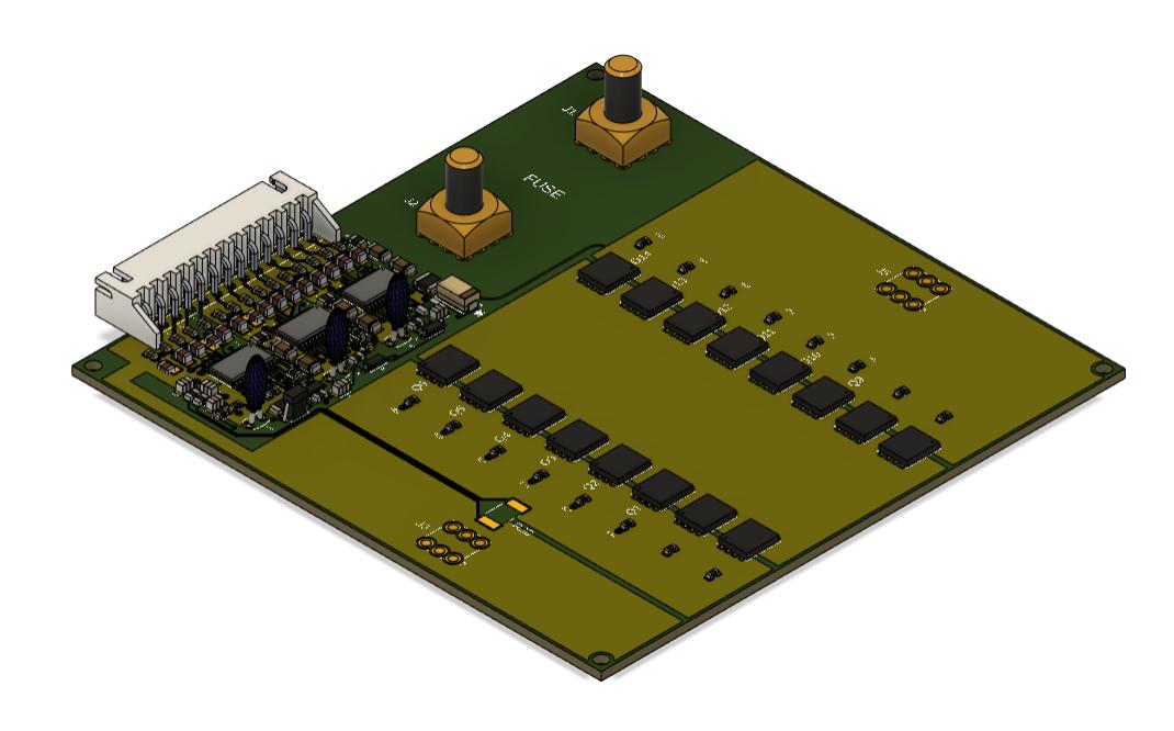
This project is a design for a BMS (battery management system) circuit for a lithium-ion battery. It was going to be used for an electric skateboard, but I decided that I wanted the skateboard sooner than later, so I bought a commerical BMS and put this design on hold. A BMS circuit is a protective measure that is commonly used when working with lithium-ion batteries. The BMS monitors a battery pack and turns off the pack when it senses unsafe conditions, such as a high temperature, or a high current. I designed the schematic and layout for the circuit using Fusion 360 ECAD. The three images below show the circuit schematic, the circuit layout, and a 3D representation of the finished circuit. The circuit is not quite complete. There are still a few traces not yet routed in the layout, and the silkscreen labeling is not complete.
BMS Schematic and Layout

The BMS design above is built around the IC chip named BQ77915 which is made by Texas Instruments. In this design, there are three BQ77915 chips, and they can be seen in the upper center of the circuit schematic, and in the bottom left of the layout. The BQ77915 chips act together as the “brain” of the system which monitors and controls the flow of electrical signals throughout the circuit. The BQ77915 chips can turn on or off a set of MOSFETS (which are functionally electronic switches in this project) to allow or prevent the flow of electricity into or out of the battery. There are a total of 16 MOSFETS in this design, 8 are in parallel and can turn off power during charging, and the other 8 in parallel turn off power during discharging. The reason there are so many MOSFETS in parallel and the wide trace widths is to dissipate large power during operation, as the BMS is made to handle 75 amps of continuous discharge current from the battery.
MOSFET Calculations

Equations
- Power Dissipation per MOSFET = (max Current/parallel MOSFETS)^2 * (drain-to-source resistance of MOSFET)
- Change in Heat per MOSFET = (power dissipation per MOSFET) * (junction-to-ambient thermal resistance of MOSFET)
- Temperature Change Difference = (Change in heat per MOSFET current) - (change in heat per MOSFET previous)
The chart above shows the calculations for one of the MOSFETS considered for this project. The parameters on the left were taken from the datasheet of the MOSFET. The table shows the power disspation and heat generated per MOSFET when a continous 75 amps is ran through the BMS.
BMS 3D Model
 Above is a 3D representation of the final circuit. In the top right of the circuit you can see a spot to put a fuse. This acts as a secondary protector just in case something goes wrong with the BMS during operation. Before I finalize my design, I may remove the fuse holder off of the PCB and just add it as a separate piece inside the housing for the electronics on the electric skateboard. The fuse will connect between the positive lead of the battery and the speed controller (the circuit that controls the speed of the electric motors). In the 3D representation above, parts of the board are a lighter green and other parts are a darker green. The lighter green represents copper tracings which are the conductive parts of the board, and the darker green represents parts of the board that have no traces and are non-conductive. The fuse holder is mounted on a non-conductive part of the board, as you only want electricity from the positive lead of the battery to flow through the fuse and not into the board. The negative lead of the battery would connect to the J3 connector location (on the bottom of the board located on the light green portion of the board) and flow through the MOSFETS to the J5 connector location (directly above the J3 connector at the top of the board). As mentioned previously, the BQ77915 chips can turn off the MOSFETS to prevent current flow from in or out of the battery.
The circuit design is not quite complete, but once it is I plan to send the design files to a PCB manufacturer to have the circuit made. I am hoping to have the manufacturer assemble the board as well, but if I think that is too expensive, I may modify the design to make hand soldering easier, or I may look into other solder options, like reflow soldering. Once the board is designed, I will test it to make sure it works as expected, then install it into the electronic skateboard.